1. Why should the interface be upgraded?
In an industrialized production environment, everything revolves around reliability, productivity and stability. Processes and equipment are subject to multiple certifications. All changes are properly planned and tested in advance. No one wants to be dazzled or overwhelmed by the infinite possibilities offered by technologies that are still in their infancy. And it's reasonable to be reasonably skeptical of new things. It is true that in any case, the optimization of processes and workflows requires the use of technology in the number of passes. And how to judge that the technology is really mature enough to be deployed, and determine that the risk of technology application is minimal? What would society be like today if new technology had never been applied? If we just stick to the technologies that others have tried and tested, and rely on the one-sided knowledge of our predecessors, how can we cause this fourth industrial revolution?
2. Transition Technology
About five years ago, some cameras used USB 3.0 technology. For the first time the USB 3.0 interface meets the tried-and-true digital camera interface in industrial machine vision, the results are clear. USB 3.0 brings the following advantages:
A> extremely fast
B>Perfect for industrial applications
C>Easy to use
D> Universally applicable
However, at that time, the development logic of the USB 3.0 interface only showed the tip of the iceberg of its huge potential.
Since the introduction of the USB 3.0 interface, from the initial incompatibility problem to the full maturity, the USB 3.0 interface has gained most of the support. As the saying goes, if you don't accumulate a few steps, you can't go a thousand miles. The following are the reasons to support the upgrade of the USB 3.0 interface:
A>The life cycle of USB 2.0 products is coming to an end. As a result, it becomes harder (and more expensive) to get the matching hardware and support
B> In 2012, Intel launched the Ivy Bridge processor, making USB 3.0 the mainstream interface
C> Current chipsets such as the Intel Sunrise Point chipset (Skylake architecture) represent another milestone. USB 3.0 Controller Interface (xHCI) supports all USB speed types for the first time
1> Low speed (1.5 MBit/s)
2> Full speed (12MBit/s)
3>High speed (480MBit/s)
4> Overspeed (5GBit/s)
Therefore, the USB 2.0 Hi-Speed Controller (eHCI) is no longer integrated
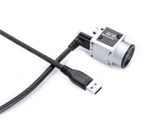
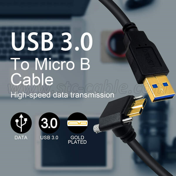
3. Getting Better - USB 3.0 Micro B Cable
Use the USB 3.0 interface to maximize the full performance of the latest CMOS sensors.
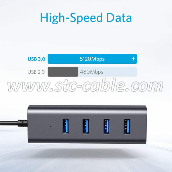
4. How the USB 3.0 System Works?
USB 3.0 doubles the amount of image data that can be provided to applications. However, data transmission in the gigahertz range requires all relevant system components to be certified and certified for quality.
Comparing a USB 3.0 camera to a Formula 1 car, it doesn't run smoothly. The maximum speed cannot be reached with ordinary unleaded fuel. And USB 2.0 is like a mid-range car, with every cable transferring USB data at high rates effortlessly. When the target bandwidth is so low, neither the quality nor the tolerance of system components becomes irrelevant. USB 2.0 itself is the bottleneck.
Therefore, the performance of a USB 3.0 SuperSpeed system does not depend on the specific camera used and the corresponding package in the computer system. In this case, system performance is determined by system shortcomings. USB 3.0 strives to achieve data rates that are supported by all components in the transport chain. Because of the huge leap in performance that USB technology brings, all system components must always run at full capacity with no major fault tolerance.
Let STC-Cable Helps you choose the right accessories and helps you identify and eliminate any weaknesses.
1. High-quality cables are indispensable
What exactly does "high quality" mean and why is it so important to USB 3.0? To answer these questions, we must first figure out what the role of the cable is and what requirements it needs to meet.
A cable creates a pluggable, flexible, and long enough connection between two devices to transmit electrical signals or power between them without any loss.
This shows that both mechanical and electrical factors can interfere with the proper functioning of the cable - such as loose plugs, kinked or frayed copper wires, weak signal strength, etc.
Traditional copper-based passive cables are limited by a set of basic physical rules. Often, these rules make it difficult for cable manufacturers to produce an ideal cable that meets all requirements. Therefore, this scheme must be adopted!
Physical line resistance can attenuate high-frequency data signals, such as USB 3.0 (5GHz) signals. The longer the copper wire, the smaller the diameter. The resistance is stronger. The resulting signal loss is called insertion loss.
Increasing the cable diameter can reduce the line resistance. In other words, the thicker the copper wire in the USB 3.0 cable, the better the transmission performance of the cable for high frequency signals. The AWG (American Wire Gauge) value indicates the diameter of the wire. The lower the AWG value, the larger the diameter and the lower the line resistance. This also increases the overall thickness of the USB 3.0 cable, reduces cable flexibility, and makes connector installation more difficult.
In short, there are many aspects of the USB 3.0 cable production process that can go wrong. In particular, cables produced for consumption at low cost and simple processes often do not meet production quality standards, do not meet the stringent requirements of industrial environments, and result in increased USB transmission errors and dropped connections. The end result is that transmission performance is degraded, or the connection is unstable.
Reduced transfer quality can cause cameras with USB 3.0 hardware to be registered as USB 2.0 high-speed devices when establishing a connection with the camera driver. This is due to the USB port used and its internal wiring.
2. Cable length
The USB 3.0 specification is not limited by the maximum cable length. The reason is the relationship between the cable length and the associated high frequency performance or voltage drop, both of which constrain each other. If the impact of these factors can be minimized, longer and functional cables can be produced.
STC has experienced USB cable manufacturing technology to support the development of high quality and efficient cables. We are also working to provide longer passive cables for a variety of different applications. In order to ensure the quality of the line, according to the requirements of the technology, the diameter of the 5-meter and 8-meter cables should be larger. With the support of strong partners, we can ensure a stable and reliable connection between cables and plugs.
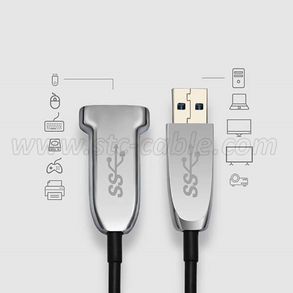
So you don't need to switch to a different camera interface when your application requires cables longer than 8 meters. Active fiber optic cables also sustain long-distance USB 3.0 data transfers at high data rates
STC sells off-the-shelf USB optical cables (Active Optical Cables - AOC) up to 50 meters long. If necessary, you can get passive cables directly by sacrificing cables. The electronics required for signal processing and amplification are integrated directly into the connector. Nonetheless, the length and thickness of these connectors are only slightly longer and thicker than the corresponding edgeless connectors.
In addition to the fiber optic material, the connector also integrates a copper-based power cord. AOC cables are called "hybrid" cables. This shows that the camera can be connected to the host through a cable and powered directly by the host. Supply voltage through the host USB port while powering the camera and cable electronics. An optional Y-USB cable can be used to connect a second USB port to complement the first port to secure power for energy-intensive devices.
3. The "correct" USB 3.0 connection
Note: Even if the port is clearly identified as a SuperSpeed USB 3.0 port, there will still be some inferior and fake USB 3.0 ports that will affect your experience.
Front ports are bridged to the motherboard by cables inside the computer. Therefore, these ports are governed by the same rules that apply to the cable connection between the computer and the camera. Still, most cable accessories are not USB 3.0 compatible.
Poor shielding of plug connections or exposed cables
The extra plug connection of these "cable extension cables" between the camera's USB controllers negatively affects signal quality.
Whether these ports can provide sufficient and stable power supply is still questionable.
Additionally, multiple front-end ports are often connected through the same USB controller. These ports share the maximum allowed USB 3.0 bandwidth. So if you want maximum throughput, avoid running multiple cameras at once.
The computer's rear ports are firmly soldered to the motherboard, and there are no problems with cables or connectors when using these ports. However, past experience has shown that the performance of these ports can vary widely depending on the number of motherboards and the operating system used. Therefore, we cannot conclude that these back-end ports are generally suitable for high-performance USB 3.0 data transfer.
Chipset drivers also play an important role. Since these drivers are responsible for many other hardware components in addition to the USB controller, we maintain and upgrade these drivers whenever a new generation of processors comes along. Therefore, to avoid system software errors, drivers must be maintainable and manageable. Obviously, system developers don't offer unlimited new hardware updates for older operating systems. Not long ago, Microsoft announced that it would stop providing Windows 7 support for Intel's current Skylake processor architecture.
4. USB 3.0 multi-camera system
In a multi-camera system, when the number of cameras is small, the data throughput is larger; when the number of cameras is larger, the throughput per camera is smaller. Again, the type of application you use will determine the number of cameras running on the host system, as well as data bandwidth and cable length.
The same rules that apply to stable USB 3.0 systems apply when building a multi-camera system. If you follow these rules, unexpected failures can be avoided.
Trying out the components provided by STC makes it easy to build a stable USB 3.0 multi-camera system. Even a 50-meter USB 3.0 active optical cable doesn't cause any problems for multi-camera operation.
There are two things to keep in mind when building a multi-camera system:
1>To ensure that all cameras have the required data bandwidth, the host system needs to have a sufficient number of high-performance USB 3.0 ports.
2>For reliable operation, you need to provide adequate power supply to all connected cameras.
The USB controller establishes a connection between the USB data and the virtually unlimited high-speed data channel within the computer. Each overdrive controller uses a fraction of this data channel to meet your application needs. If only one USB port is connected to the controller, it means that a single consumer device can monopolize the entire USB 3.0 bandwidth.
This 1:1 connection is the most powerful configuration for a camera. The greater the number of ports available in the system but the controller, the more the multi-camera system can benefit from the performance or performance of the internal data interface. You can try a USB 3.0 PCI Express card to make sure you get the most out of these controller ports.
If your camera doesn't need to use the full USB 3.0 bandwidth, it can be shared among multiple data-providing devices.
You can use a USB hub to make a 1:n connection. Make sure that all connected cameras at each distribution point have adequate power supplies. A powered USB hub can provide additional power from a separate power supply.
However, this is also where the potential pitfalls of multi-camera applications lie. If manufacturers cut costs where they shouldn't in order to lower prices, the size of the built-in hardware will not be suitable for speed camera applications, which in turn leads to lower voltages and even power outages. In these cases, the stable operation of the camera cannot be guaranteed.
Therefore, STC uses only non-defective USB hubs in its product portfolio, which operates normally in all compliant states. In other words, STC will only provide you with the right components to ensure you can build a stable, high-performance multi-camera system.
5. Summary
Converting camera interface technology to USB 3.0 is a general trend. USB 3.0 is now a mature technology, and its use is rapidly expanding. The USB 3.0 interface is the ideal data interface for new applications with modern sensors.
We have accumulated a wealth of knowledge and experience related to USB 3.0 technology, as evidenced by the way cameras and accessories have evolved.
Send your message to us:
Post time: Apr-26-2022