USB Type-C is a specification for a USB connector system that is gaining popularity on smartphones and mobile devices and is capable of power transfer and data transfer. Unlike USB's earlier offerings, it's also reversible - so you don't have to try plugging it in multiple times.
1.What is USB-Type-C
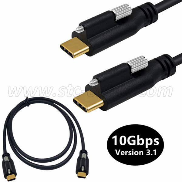
USB-C is a relatively new standard designed to provide high-speed data transfer up to 10Gb/s and power up to 100W. These features could make USB-C a truly universal connectivity standard for modern devices.
2.The USB-C interface has three main functions:
1>It has a reversible connection port. The interface is designed so that the plug can be flipped over relative to the socket.
2>It supports USB 2.0, USB 3.0 and USB 3.1 Gen 2 standards. In addition, it can support third-party protocols such as DisplayPort and HDMI in an operational mode called Alternate Mode.
3>It allows devices to negotiate and select the appropriate power flow through the interface.
3.Signal diagram
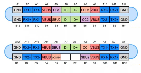
The USB Type-C connector has 24 pins. Figure 1 and Figure 2 show the pins for the USB Type-C receptacle and plug, respectively.
4.USB 2.0 differential pair
The D+ and D- pins are a differential pair for USB 2.0 connections. There are two D+ pins and two D- pins in the socket. However, these pins are connected to each other and there is really only one USB 2.0 data differential pair available. The redundant design is just to provide reversible connectors.
5.power and ground pins
The VBUS and GND pins are the return paths for power and signals. The default VBUS voltage is 5 V, but the standard allows devices to negotiate and select a VBUS voltage instead of the default. Power delivery allows VBUS to have up to 20 V. The maximum current can also be raised to 5A. Therefore, USB Type-C can provide a maximum power of 100 W.
High power flow can be useful when charging large devices such as laptops. Figure 3 shows an example of RICHTEK where a buck-boost converter is used to generate the appropriate voltage requested by the laptop.

Note that power delivery technology makes USB Type-C more versatile than older standards because it adapts power levels to the needs of the load. You can use the same cable to charge your smartphone and laptop
6.RX and TX pins
There are two sets of RX differential pairs and two sets of TX differential pairs. One of these two RX pairs along with the TX pair can be used for the USB 3.0/USB 3.1 protocol. Since the connectors are reversible, the multiplexer is required to properly reroute the data on the differential pair being employed through the cable.
Note that USB Type-C ports can support USB 3.0/3.1 standards, but the minimum feature set for USB Type-C does not include USB 3.0/3.1. In this case, the USB 3.0/3.1 connection does not use the RX/TX pair and can be used by other USB Type-C features such as Alternate Mode and USB Power Delivery. These functions can even take advantage of all available RX/TX differential pairs.
7.CC1 and CC2 pins
These pins are channel configuration pins. They perform many functions such as cable connection and removal detection, socket/plug orientation detection, and current broadcast. These pins can also be used for communications required for Power Delivery and Alternate Mode.
Figure 4 below shows how the CC1 and CC2 pins show the socket/plug orientation. In this diagram, DFP stands for downstream facing port, which acts as a host or power supply in data transfer. UFP stands for Upstream Port Facing, which is a device that connects to a host or power consumer.
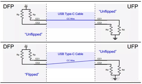
The DFP pulls up the CC1 and CC2 pins via the Rp resistor, but the UFP pulls them down via Rd. If no cable is connected, the source sees a logic high at the CC1 and CC2 pins. Connecting a USB Type-C cable creates a current path from the 5V supply to ground. Since there is only one CC wire inside the USB Type-C cable, only one current path is formed. For example, in the image above, the DFP's CC1 pin is connected to the UFP's CC1 pin. Therefore, the voltage on the DFP CC1 pin is less than 5 V, but the DFP CC2 pin is still at a logic high level. Therefore, monitoring the voltage on the DFP CC1 and CC2 pins, we can determine the cable connections and their orientation.
In addition to cable orientation, the Rp-Rd path is also used as a way to convey source current capability information. To do this, Power Dissipation (UFP) monitors the voltage on the CC line. When the voltage on the CC line has its lowest value (about 0.41 V), the source can provide default USB power of 500 mA and 900 mA for USB 2.0 and USB 3.0, respectively. The source can deliver 1.5 A when the CC line voltage is about 0.92 V. The maximum CC line voltage is about 1.68 V, corresponding to a 3A source current capability.
8.VCONN pin
As mentioned above, USB Type-C is designed to provide blazing-fast data transfer speeds along with high levels of power flow. These features may require the use of special cables that are electronically marked by using a chip inside. Additionally, some active cables utilize re-driver chips to strengthen the signal and compensate for losses caused by cables, etc. In these cases, we can power the circuitry inside the cable by applying a 5 V, 1 W supply to the VCONN pin. As shown below.
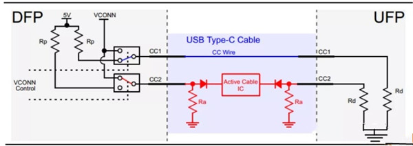
As you can see, the active cable uses the Ra resistor to pull down the CC2 pin. The value of Ra is different from Rd, so the DFP can still determine the cable orientation by checking the voltage on the DFP CC1 and CC2 pins. Once the cable is oriented, the channel configuration pins corresponding to the "active cable IC" will be connected to a 5 V, 1 W supply to power the circuitry inside the cable. For example, a valid Rp-Rd path corresponds to the CC1 pin. Therefore, the CC2 pin is connected to the power supply represented by VCONN.
9.SBU1 and SBU2 pins
These two pins correspond to low-speed signal paths that are only used in alternate mode.
10.USB powered
Now that we've gotten acquainted with the fixation of the USB-C standard, let's briefly introduce USB Power Delivery and Alternate Modes. As mentioned above, devices using the USB Type-C standard can negotiate and select the appropriate level of power flow through the interface. These power negotiations are achieved through a protocol called USB Power Delivery, which is a single-wire communication over the CC wire discussed above.
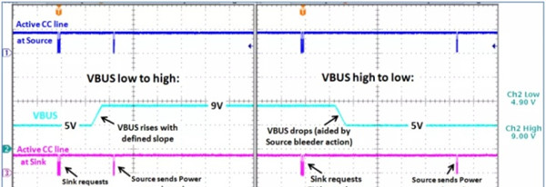
The figure below shows an example USB powered, where the sink sends a request to the source and adjusts the VBUS voltage as needed. First, a 9 V bus is required. After the source stabilizes the bus voltage to 9 V, it sends a "power-good" message to the receiver. The sink then requests a 5V bus, and the source provides it and sends the "power ready" message again.
It is worth noting that "USB Power Delivery" does not only involve power supply related negotiations, other negotiations, such as those related to the standby mode, are all done using the power supply protocol on the standard CC wire.
Send your message to us:
Post time: Jun-01-2022