USB and Quick Charge (QC) are two new power supply standards in the current market and are also market trends. A common feature of these two standards is that the output needs to be adjusted. The single-inductor H-bridge buck-boost NCP81239 is available in a wide input voltage range and wide output voltage range. It is ideal for applications such as USB type-c or QC 3.0 that require voltage regulation based on the requirements of the consumer. The chip-integrated I2C interface can be used with external (MCU) for stepping adjustment of the output voltage, and can implement multiple fast charging protocols such as USB PD type-c and QC 2.0/3.0 in the same type-c port. Apple LighTIng interface fast charge protocol, and Samsung interface fast charge protocol.
USB type-c and Quick Charge overview
1. USB Type-C
Electronic products such as computers, mobile phones, digital cameras, etc. often need to be interconnected with other electronic devices to transmit data or provide. However, adapters and cables of various specifications are inconvenient to use, and the weight of the travel bag is also increased. . In order to reduce the number of harnesses and unnecessary waste, the USB Type C interface standard came into being. The goal of the USB Type C interface is to use a uniform interface between the interconnections of different electronic devices, while providing power and transmission data, as well as audio and video and customer-specific communication protocols. The evolution of USB charging technology is shown in Figure 1.
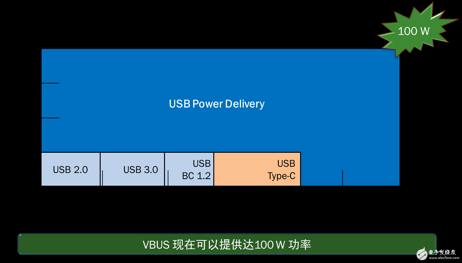
USB PD supports power supply of different power levels. It supports 5 V@2A by default when booting. It can be adjusted to 18 W, 36 W, 60 W, 100 W, etc. as needed. The cable needs to support more than 1.5 A current. The larger power output needs to be adjusted. Output the voltage to a higher value to ensure that the cable current does not exceed the specifications. In addition, the USB PD protocol also supports additional power and voltage options.
2. Quick Charge
Quick Charge is a technology developed by Qualcomm to support the rapid charging of handheld devices. The output voltage is increased by increasing the output voltage to reduce the loss on the cable and the connector. The output voltage is set by the different states of the USB signal lines D+ and D-. The QC 3.0 standard supports 200 mV/step voltage regulation to optimize the conversion energy efficiency of the handheld device's charging section and reduce temperature rise.
NCP81239's features and working principle
The NCP81239 supports a wide input voltage range, provides a dynamic switching frequency from 150 kHz to 1.2 MHz, integrates four MOSFET drivers, uses dual edge current mode control, supports output pre-bias startup, and adaptive dead time control prevents shoot-through, independent Input and output current sensing, output voltage (range 0 to 20V) can be programmed via I2C, integrated with overvoltage, undervoltage, overcurrent and accurate overload protection, as well as protection for 5 V Vconn supplies .
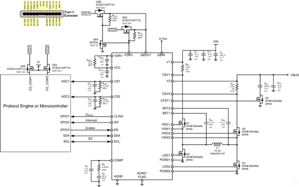
NCP81239 typical application circuit diagram
The NCP81239 features dual edge current mode buck-boost control for seamless switching from buck mode to boost mode. I⊃2; C interface uses only two signal lines for bidirectional serial communication. The open drain connection can be easily interfaced between different logic levels, compatible with 1.8 V, 2.5 V, 3.3 V and 5 V logic levels. MCU.
The input and output currents can be detected by the high-side detection. The detected voltage is divided into internal and external channels: the internal current signal is used for current mode loop control and current limit protection, and the overcurrent protection can be set by internal registers. Or shielding, the internal fixed gain is 10 times, the internal current value is stored in the corresponding register through the analog-to-digital converter (ADC), and can be read by I2C; the external current signal can be read by the MCU to perform the corresponding software operation, and the external can be Set the range of current measurement. The current-sense op amp has a transconductance of 5mS. The external resistor can also be used to filter the current signal into an average value.
The NCP81239 has a built-in 4-channel 7-bit ADC that can perform A/D conversion between input and output. The corresponding value can be read by I2C reading internal registers. The internal feedback reference voltage is set by a 9-bit DAC with a reference voltage range of 0 V to 2.55 V. The output voltage range can also be set via an external voltage divider network. Since the internal step has a 9-bit ADC and the step size is small, it is easy to set the compensation cable voltage drop with the MCU I2C interface, so that the load voltage can be kept within the error range of the set value, which is very suitable for QC3.0 or USB PD and other occasions where voltage regulation is required.
In the USB PD, QC2.0, QC3.0 and other specifications, if the output voltage is dynamically set, the voltage regulation rate will be involved. If the regulation speed is too fast, the inductor current will overshoot and the output voltage will overshoot or undershoot. The NCP81239 has built-in registers that can be set via the I2C interface to control the slope of the voltage rise and fall during voltage regulation.
The NCP81239 detects the input peak current through RS1 for forward overcurrent protection. The current limiting mode is wave-by-wave plus hiccup mode. When an overcurrent is detected in one cycle, either in buck mode or boost mode, Q1 is immediately turned off to limit input power. If the wave-by-wave current limit time reaches 2mS or the FB voltage is lower than 300mV, enter the fast shutdown mode and turn off 4 switches. After 10 mS, it will soft-start to the original set output voltage and current. The overcurrent protection value can be set by I2C or current sense resistor. The current sense resistor should be selected to ensure that the voltage of CSP1-CSN1 does not exceed 100mV of the op amp differential mode voltage range when overcurrent. If a 5 milliohm sense resistor is used, the corresponding peak overcurrent protection value is as follows, with a default value of 7.6 A.
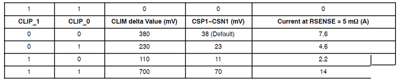
Peak overcurrent protection value for 5 mΩ sense resistor (forward overcurrent protection)
The buck-boost control of the 4-switch synchronous rectification has a reverse current generated during the light load mode, the heavy-duty to light-load conversion process, and the output and output from high voltage to low voltage regulation. CSP2/CSN2 is used for reverse current detection. When the reverse current exceeds the current limit setting value, if the output voltage is within the set voltage range, Q4 will immediately turn off to prevent the reverse current from continuing to increase. If it is in buck mode, Q4 will turn back on when Q2 is turned off. The overcurrent protection value can be set by I2C or current sense resistor. The current sense resistor should be selected to ensure that the voltage of CSP2-CSN2 does not exceed 100mV of the op amp differential mode voltage range when overcurrent. If a 5 milliohm sense resistor is used, the corresponding peak overcurrent protection value is as follows, the default value is -8 A.
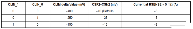
Peak overcurrent protection value for 5 mΩ sense resistor (reverse overcurrent protection)
When the output voltage is higher than the set value of 110% for more than one switching cycle, the NCP81239 enters the overvoltage protection mode. During overvoltage protection, S1 is turned off, S2 is turned on, and S3 and S4 are alternately turned on to discharge the output voltage while preventing the reverse current from exceeding the set reverse protection current value. In the event of an output overvoltage fault, the switching frequency is reduced to 50KHz, preventing the inductor from saturating while reducing the power tube.
![]()
Output overvoltage protection icon
Conventional synchronous rectification control is initiated when the output has a pre-bias voltage, and the output is first discharged and then raised. When the output is pre-biased, the NCP81239 will operate in non-synchronous rectification mode at startup and will not discharge the output. It is suitable for battery load applications.
The output voltage is within +/- 5% of the set value, and a Power Good signal is issued after a delay of 3.3mS. If the output voltage exceeds +/- 7 % of the set value for more than one switching cycle, the Power Good register is reset and the interrupt signal is output.
The NCP81239 supports four I2C addresses, which can be configured before the chip is shipped from the customer. The default I2C address is E8h/E9h.
In addition, the NCP81239 itself has overheat protection. When the junction temperature of the chip exceeds 150 degrees, it will turn off the external four switches. After the temperature drops to 125 degrees, it will restart.
Reference design
ON Semiconductor offers reference designs such as 60 N car charger for NCP81239, external docking station for laptops, desktop applications, and patch panels with Type-C interface for small size and high energy efficiency in USB PD and Quick Charge Different application requirements under specifications.
To Sum Up
The Type-C interface is becoming a single interface for interconnection between electronic products. The high voltage USB PD requires different voltages and powers to regulate the output voltage. The features and comprehensive protection features of ON Semiconductor's NCP81239 make it ideal for highly reliable applications requiring wide voltage inputs and adjustable voltage outputs, such as USB PD and Quick Charge, and battery charging, with its unique control mode. Efficient buck-boost conversion, up to 1.2MHz operating frequency for a compact design.
USB 3.1 Type C Extension Data Cable with Panel Mount Screw Hole
Send your message to us:
Post time: Mar-26-2019