RaspBerry 4 Pi model B (Raspberry Pi 4B) was officially released, and it has upgraded its processing capabilities, communication methods, and external interfaces, bringing the gospel to embedded developers. After receiving the goods, many developers started to try with excitement. As a result, it was found that the USB-C interface has serious problems in design specification.
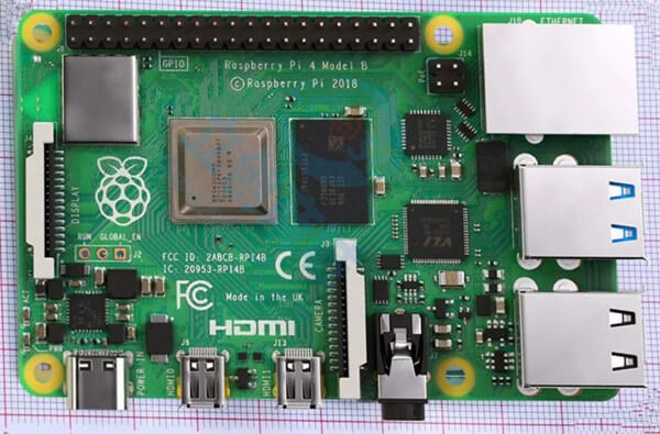
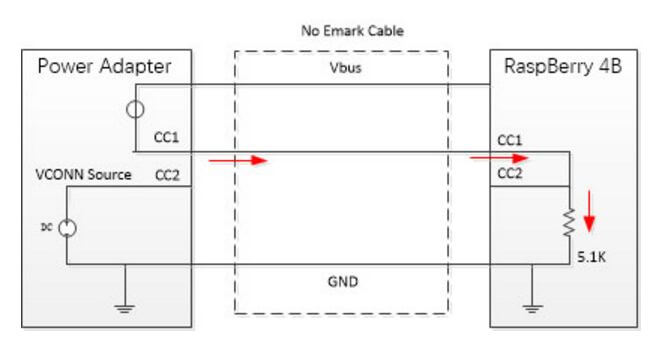
After actual testing, the USB-C interface on the Raspberry Pi 4, CC1 and CC2 are connected together, and share a 5.1k resistor to the ground. This design seems to be very clever, the control of the USB-C interface is extremely simple, only a 5.1k pull-down resistor is needed. When the external USB-C Cable does not have an Emark chip, it does work. Because the CC2 of this type of USB-C Cable is floating, only CC1 is connected to the opposite end. Therefore, this cable is connected with the USB-C interface socket of RaspBerry 4B, which is very good in conformity with the design specifications of the Sink. That is, on CC1, there is a 5.1k resistor pulled down to ground.
However, in the USB TYPE-C specification, a cable with an Emark chip is also specified. On the CC2 of the Cable, there is a 1K pull-down resistor for informing the CC of the DFP to identify the chip. VCONN Source is required to be supplied to CC2. . Once connected to such a cable, RaspBerry 4 Pi model B will have serious problems. Because CC1 and CC2 are connected, they will be connected in parallel with the 1K to ground resistance on the Cable to form a smaller impedance than the 1k resistor, thus satisfying the connection specification of the Audio Adapter Accessory Mode in the USB-C specification, which is mistaken by the power supply. It is an analog headphone device that refuses to supply power.
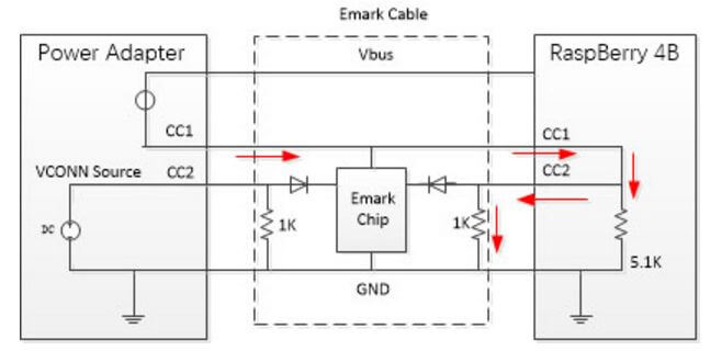
From the above figure, we can see that the 1k resistor on the Emark connection will cause CC1 to fail to establish. The parallel connection of the 1k resistor and the 5.1k resistor will cause the RaspBerry 4B to be considered an Audio Adapter Accessory Mode. The solution to this problem is also very simple, just need to connect a 5.1K resistor to ground on CC1 and CC2, independent of each other. This can be searched for the author's original article in 2015, "Do you really need TYPE-C chips?" This article provides three principles and two implementation methods for judging whether the system needs to use the USB-C control chip.
RaspBerry 4B's design on the USB-C interface is actually an entry-level design, because this interface is only used for 5V power supply and a USB2.0 communication, no complicated audio and video and USB3.0 functions. In actual embedded development, the functionality of a USB-C interface may be much more than that. Below we explain the three points of high-power power supply, high-speed signal transmission, and dual C-port DRP control.
First, you need to use the USB-C interface to get the 9V/12V/15V/20V supply voltage. Many embedded systems have very complex functions, and only 5V power supply is not enough. Then, at this time, it is not enough to set the 5.1k pull-down resistor separately on CC1 and CC2. Instead, it is necessary to use the USB PD control chip. It is better to have a USB PD control chip that can flexibly configure various voltages, such as LDR6015 and The LDR6021 can do this. In some system designs, even the USB PD control chip is automatically determined to determine the highest power of the adapter, so that the power adapter can directly supply the highest power to the embedded system. At this time, the LDR6015Max can be used, which can be directly obtained without any control. The highest power.
Second, application development using high-speed video signal transmission using the USB-C interface is required. USB-C interface can support 10G/b USB 3.1Gen2 data transmission and 4K HD video transmission at the same time. But to get the Sink terminal into the DP ALT mode, you must use a USB PD Controller, such as the LDR6282. This type of USB PD control chip acts as a traffic controller and configures the high-speed differential pair path in the USB-C Cable through USB PD communication to adapt the data and video signals to the appropriate differential pair. .
Third, dual C port DRP function control, many embedded applications not only use a single USB-C port, but also may have two USB-C ports, one C port for power supply and the other C port for high speed Data and video signal transmission. However, during the user's use, it is not certain which of the two ports will be plugged into the power supply, or the multimedia device, so it is necessary to satisfy the dual C port blind insertion identification and control. The most typical application is the USB-C interface display and projector. This is a more complicated USB PD control function. Currently only LDR6282 is available on the market to meet this demand.
In summary, we can see that for the embedded system where the USB-C interface is only used for power supply and Debug function, the USB-C interface does not need to use any chip control, and a 5.1k resistor is independently pulled down by CC1 and CC2. Go to the ground. For embedded designs that require high power or HD video transmission, the USB PD control chip must be used.
Send your message to us:
Post time: Jul-31-2019